MegaView is an add-on accessory for the MegaSquirt Electronic Fuel Injection System, providing real-time display of all engine operating parameters, and allowing for the edit of any configuration variable in the MegaSquirt ECU. This dual-function device was designed to be mounted in an automotive dashboard to provide feedback on all critical engine parameters or housed in an enclosure for use as a portable tuning device.
Features:
The configurator mode will allow the user to adjust any of the configuration parameters. This is useful for field-tuning and variable tweaking. It is not designed to replace the PC Configurator for tuning, but allows for simple parameter modification as needed.
There are versions of MegaView for MS and MS-II. Because of the complexity of the latter
the MS-II version has most display variables, but only a limited set of user inputs,
with no capability to modify tables - only selected individual variables. A Celsius version
of MV-II is not needed because MS-II can be configured to operate in F or C.
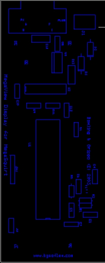
MegaView Board PCB Layout in PDF format
MegaView Source Code for MS-II
MegaView Source Code for MS-II(CAN)
MegaView S-Records (Celsius Version)
MegaView S-Records (24 col Version)
MegaView S-Records (Celsius, 24 col Version)
MegaView S-Records for MS-II (24 col Version)
MegaView S-Records for MS-II(CAN)
MegaView S-Records for MS-II(CAN) (24 col Version)
Assembly of MegaView is similar to Megasquirt, but much easier since there are fewer parts. Start
with the power section. Note that the power regulator (LM7805) is to be bent over and bolted
directly (with some heat sink grease) to the large copper pad. Note also that the + terminals for
the 2 tantallum capacitors, C13 and C14, are not marked on the pcb, but the + leads should go in
the holes closest to the C13, C14 labels. When done, verify there is 5V
at the output of the LM7805 when you put 12V and ground into the power terminal block. The
positive side of this terminal is closest to the db-9 connector and should be marked in some way
to avoid mistakes when connecting it in the car.
When done, proceed to the CPU and communication sections. If an oscilloscope is available, you
can scope the oscillator output of the CPU. The communications can be tested by hooking up the
db-9 to the com port of the pc and using Hyperterm to see if a character is sent to the ECU
requesting data.
The last three steps are:
(1) Solder the 2x7 male header to the back side of the MegaView pcb.
(2) Solder the 2x7 female receptacle to the back side of the VFD pcb. This will allow you to
plug the 2 boards together. But to maintain stability you need to install the 4 hex standoffs in
between the 4 holes on each pcb. You will need an addition set of standoffs of whatever length is
best for your application that will screw into the supplied 4 standoffs and mount the VFD to
the dash or enclosure.
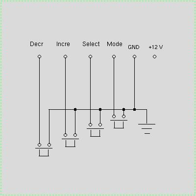
(3) Solder the single row, 6 pin header to the top side of the MegaView pcb. Mark the #1 pin (square pad)
on the board, because this is the connection to the last pushbutton (Decrement toggle). The next
3 pins go to the next 3 buttons, and the fifth pin is ground. THe sixth pin is +12 V which can be used
for wireless key fob control. The wiring is as follows:
When a button is pushed, it connects the corresponding CPU pin, which is normally pulled up to +5V in
the CPU, to ground. The pulse triggers an interrupt in the CPU and it then acts on the button push. To
install in a car, you need to get a Molex 5 or 6 pin connector and corresponding pins and make
a cable. The plug, on which the no. 1 terminal should be marked, goes on the header, and the 5 wires
go to the buttons which are mounted in a piece of sheetmetal or plastic located wherever you want -
generally close to the VFD display. Note that you can put the buttons in whatever order makes the most
sense to you and you can label them as shown in the figure. For additional assembly notes and photos see:
You are now ready to install and test MegaView in the car !! Simply mount the unit on the dash
or in an enclosure, supply +12V and ground wires to the power terminal block, and connect the
db-9 sockets on MegaSquirt and MegaView with an RS232 cable. Turn on the ignition - you don't
need to crank - and you should see the display scrolling.
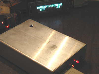
When power is applied it takes about a second for MegaView to initialize the VFD and start up. By
default, it comes up in Runtime Display Mode, as a ticker tape scroll, which is the primary intended usage mode.
If it is desired to freeze a particular variable, one may push the Select button.
This causes the scrolling action to cease, so the selected variable may be viewed continuously. Pushing
this button again unfreezes the scroll. The increment/ decrement buttons do
nothing in this mode. The only other item of note is that, if any variable begins to flash, it is a sign
that it is out of range, for example, the coolant temperature may be excessive or the sensor broken (railed).
By pushing the Mode toggle button one enters Configurator Mode. This mode starts by displaying the
first of the configuration parameters. (These are the parameters you change in the PC tuning programs.)
By pushing the increment/ decrement buttons you cause the display to scroll to the next or the previous
parameter. Holding the button down causes a continuous scroll. When you reach the parameter you want to modify,
you can hit the Select button. This causes the word 'Selected' to appear on the top line, and means
that in this submode hitting the increment/ decrement buttons will cause the parameter to increase or
decrease in value, *** and will affect operation of the car ***. Clearly one should use CAUTION
in doing this, especially while driving. When the variable has been modified as desired, hit
the Select toggle again (Unselect). This will cause ALL parameter values currently in RAM to be burned
into flash, so the modified parameter value will continue to be used on the next restart. The
'Selected' string on the top line will disappear, and you can now move to another configuration
parameter using the increment/ decrement buttons, or you can return to the Runtime Display Mode by
pushing the Mode button.
Note: if you don't want the change burned in flash permanently, then don't hit the Select toggle to Unselect
it, but instead hit the Mode toggle. However, if you later return to the configure mode and select
and unselect another parameter, then both of the modified parameters, which are now in RAM, will be burned
in flash. So if you make a change and don't want it to be permanent, then restore its value before exiting
Configure mode. But note also that if you DO want the change to be permanent, you must Unselect it with the
toggle.
Download Files for the MegaView Dash Display/Configurator Board:
MegaView Bill Of Materials
QTY   Description
---------------------------------------------------------------
(7)	C1,C5,C7,C9,	0.1
	C10,C11,C12
(1)	C2		0.033
(1)	C3		0.01
(1)	C4		50 pf
(1)	C6		20 pf
(2)	C13,C14		33 tantalum
(2)	D1,D2		1N4001
(1)	R1		10K
(1)	R2		100K
(1)	R3		10M
(1)	Y1		32.768 KHz
(1)	U1		MC68HC908GP32CP
(1)	U2		MAX232CPE
(1)	U3		LM7805
(1)	JH1		6-pin,1 row pcb header (0.10 spacing)
(1)	DISP1		Vacuum Flourescent Display
(1)			VFD receptacle (on VFD board) 2x7 contacts, .340" high
(1)			2x7 pcb male header, .320" high + 0.1" base
(1)	P1		DB-9, male
(1)	J1		Power block terminal, 2 contacts
(8)			Al hex standoffs, 1/2", 4-40, male to female
(5)			4-40 nuts to hold standoffs & LM7805 to pcb
(5)			4-40, 1/2" screws for 7805 & MV dash mount

	Additional parts NOT supplied:

		4 momentary pushbuttons
		1 Bezel
		parts for cable to connect pushbuttons to the pcb
MegaView Assembly, Installation and Usage