Additional MegaView Assembly Notes
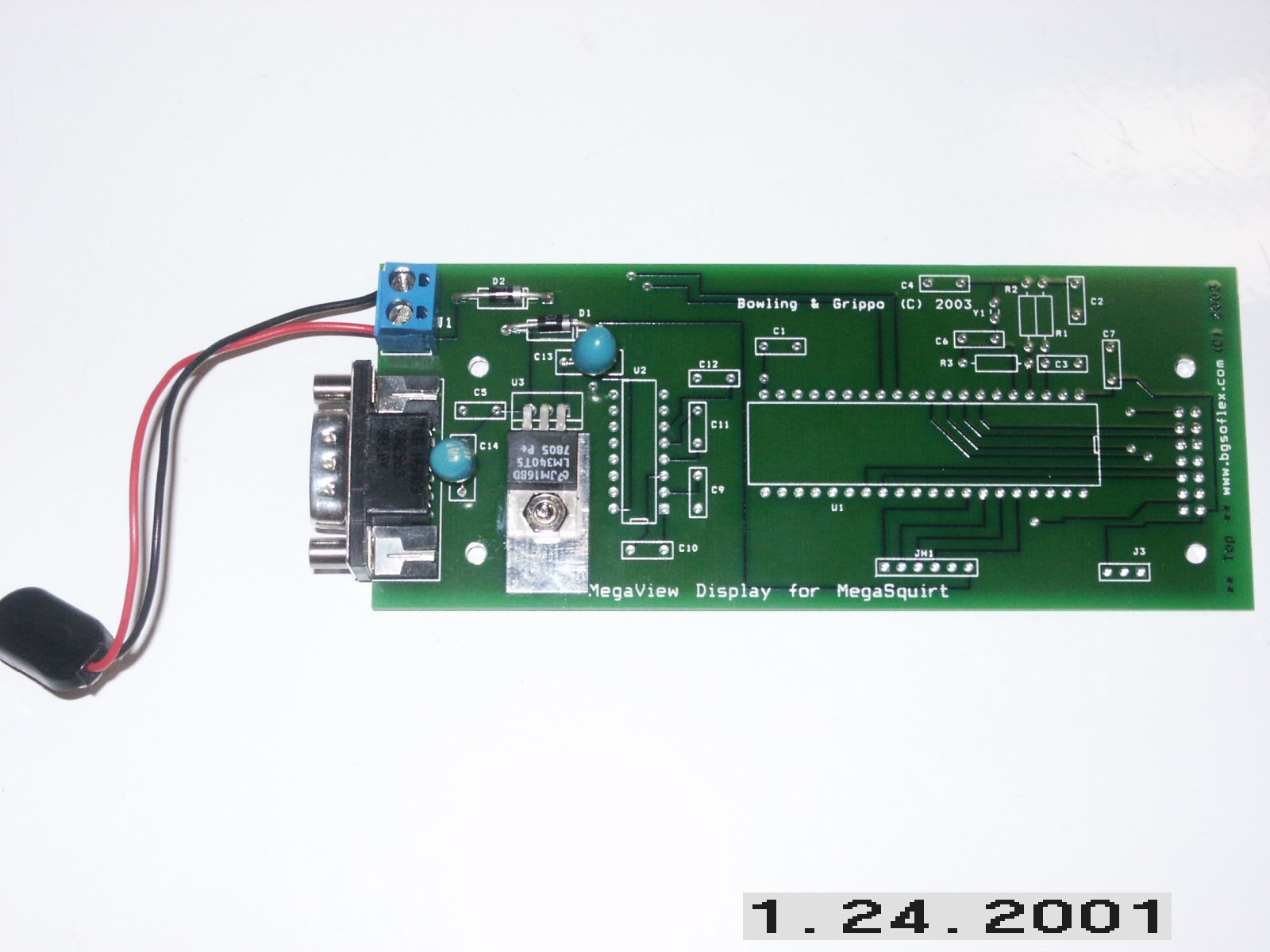
Here is a picture of just the power supply components installed. Be sure
that C13 positive lead is towards the side of the board with the DB-9
(left-hand side on picture below - you can see the trace run from this to
the voltage regulator). For C14, the positive lead is to the top of the
board (see picture - look for the trace again which runs to the voltage
regulator). You can also see the 9-volt battery clip hooked to the power
block - black wire is gnd, red (top side of block)is positive. I verified
the +5V source in this picture. Picture:
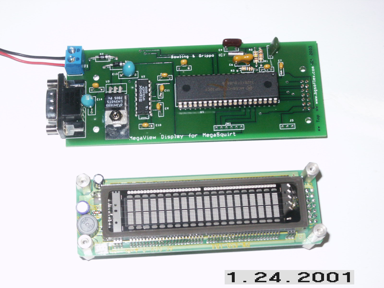
Here is a picture with the entire MV populated. Note that the header on
the MV PCB is on the bottom - this is why the PCB is not sitting flat on the
table. Next to this is the display with threaded standoffs mounted:
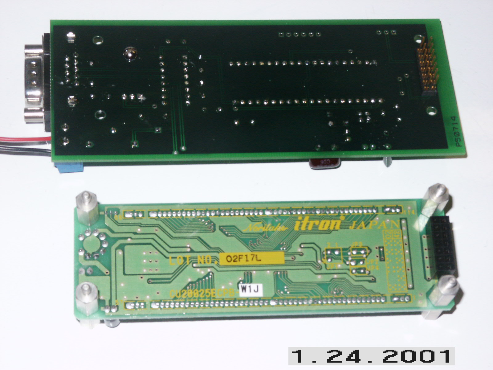
Next is a picture of the bottom side of the board. Note the header on the
bottom of the board, and the corresponding socket on the display (bottom
side of display):
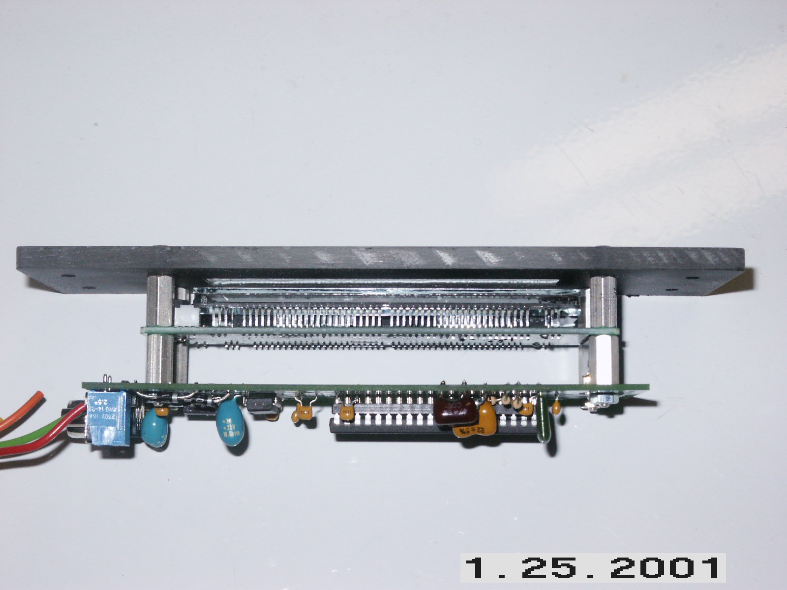
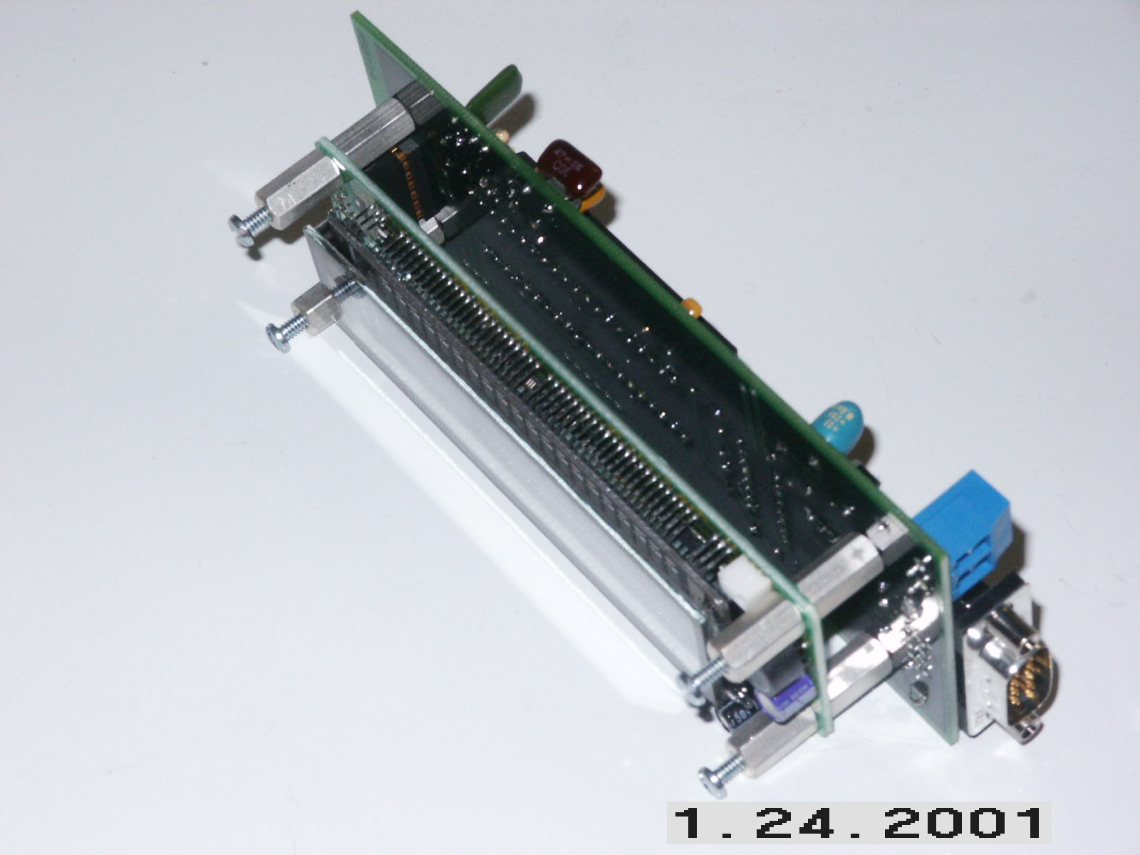
Here is an image of the two boards together with the hex standoffs holding
them together. The display is plugged into the MS board:
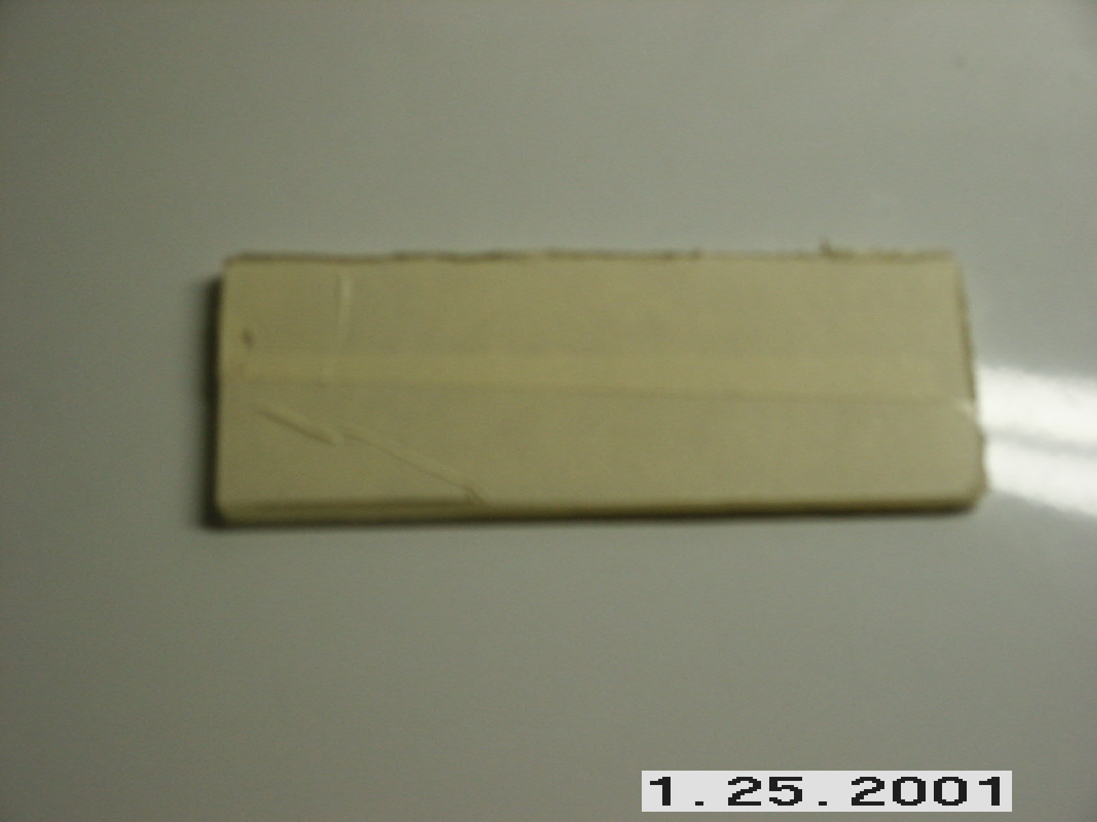
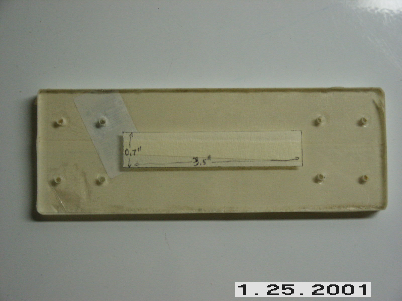
The next images just extra - it is my attempt to make up a simple front
panel bezel out of 3/16'' Lexan. I cut out a piece, taped it up with
masking tape, drilled mounting holes, made cuts around a display "window",
then I pulled all of the tape off of this side other than the center
window, painted the Lexan with black paint, removed all the tape, and
finally assembled:
Tape:
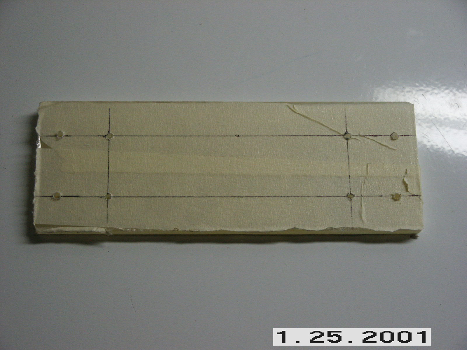
Drill:
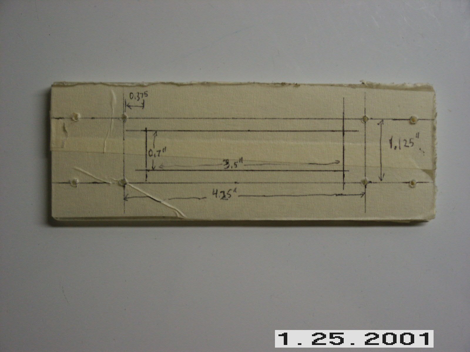
Measured window:
Cut out around the center window, and removed the surrounding tape, ready
to paint with flat black paint:
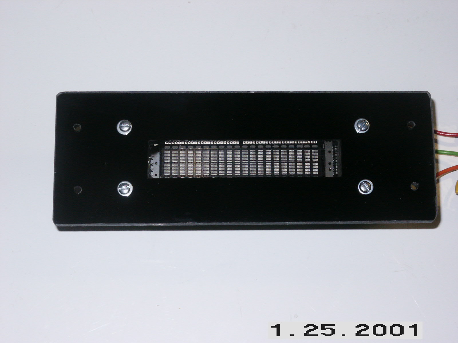
Painted the one side, then installed the MegaView using the hex standoffs.
Note that the painted side is on the inside:
Edge view of MV, display, and bezel, mounted with the hex standoffs: