|
|---|
| Home |
|
|
Software | Stimulator | MegaSquirt ECU Page |
|
This page discusses various stimulation circuits in order to fully exercise the Ford EDIS module on the bench. Using these circuits, one can simulate a spinning crank wheel with the thirty-six minus one tooth count, and supply the correct SAW pulsewidth to set a desired advance.
Variable Reluctance Sensor SimulatorTo get a Ford EDIS module firing on the bench (with a fixed 10-degree advance), all you need to supply is the proper VR sensor signal. One way is to rig up the Ford "36 - 1" tooth wheel on a variable-speed motor, and afix the VR sensor nearby to pick up the tooth signal - just like on the car. This can be done with a little effort, but there is an easier way to acheive the desired VR sensor signal. We developed a simple VR sensor simulator using a Motorola MC68HC908QT4 microcontroller. This is the now-famous 8-pin microcontroller that sells for less than a buck! Using this, a few resistors, and a power supply, add a little code, and you get an instant VR stimulator:
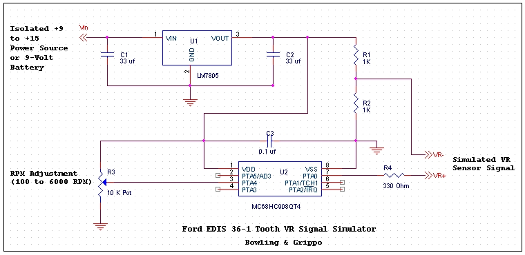 Click here for VR Simulator Assembly Code Click here for MC68HC908QT4 Equates File (required for assembly) Click here for VR Simulator Assembled .S19 Hex file ready for download The circuit is extremely simple. A 10K potentiometer is wired up to generate a 0 to 5 volt signal to the AD2 channel on the QT4 processor - this is used to set the desired simulated crankshaft RPM. The software reads the ADC port's resultant ADC counts, and then performs a lookup table function for setting the period for the timer channel in PWM mode. This lookup table has RPM table values from 50 RPM to 6000 RPM - enough for average testing. The timer for the PWM is running at 1 microsecond increment. The duty cycle of the PWM is set to 50%. Logic is put in the software to "throw out" every 36th tooth. The timer output is on pin 7, and is presented into the EDIS module VR+ input. One thing to note is that the output of the PWM port is a squarewave (0 to 5 volt), not a sinewave. Also, the signal is unipolar - the VR sensor signal requires a negative voltage swing thru zero in order to trigger. But, one can use two resistors (R1 and R2) to create a DC bias of 2.5 volts, and this is presented on the other VR input, such that the square wave now has a +/- 2.5 volt swing. And, the EDIS module does not care that the signal is a squarewave - as long as it passes thru zero and has the proper cadance of "teeth" it will trigger all day long. Another thing to note is that since the ADC counts map into RPM values via a lookup table, one can generate any mapping they desire in software. The current software will give RPM values from 50 to over 6000 RPM in a linear fashion. In order to generate any other range of RPMs requires only to re-generate the lookup table with the desired values. The final thing to note here is since this circuit presents a +/- 2.5V differential signal to the VR sensor, it's power supply needs to be isolated from the EDIS +12V power supply, including the ground circuit. I used a 9-volt battery for the simulator, but any power supply from 9 to 15 volts will work.
EDIS SAW Advance Word Simulator
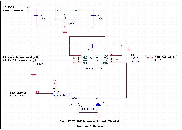 Click here for EDIS SAW Advance Pulse Generation Assembly Code Click here for MC68HC908QT4 Equates File (required for assembly) Click here for VR Simulator Assembled .S19 Hex file ready for download This circuit is very similar to the VR sensor stimulator but with the added usage of the IRQ port for detecting the PIP waveform from the EDIS module. The SAW pulsewidth is determined from the pot voltage (ADC channel performs a conversion and uses the result in a lookup table for SAW pulsewidth). The table has advance widths from 1 degree to 59 degrees, but can be modified to generate any width. This module can be run from 9 volts to 15 volts. The easiest power source to use is the same 12-volt supply powering the EDIS module. Be sure that the grounds are common if using a separate power supply.
Complete EDIS Bench Test StandWith the two circuits above we can create a EDIS Test Stand and exercise the EDIS module, both RPM and advance. We used an EDIS-8 module in our test stand, including the two coil-packs. We mounted eight spark plugs on an aluminum angle-iron and ran the HV spark plug wires back to the coil packs (be sure to ground the aluminum strip to common ground on the EDIS module). The rest of the wiring of the EDIS module was to the VR stimulator and the SAW advance simulator. We used a 10-amp, 13-volt power supply to power the EDIS module and the two coil packs, and the SAW simulator. A separate power source (9-volt battery) was used for the VR stimulator. To monitor the operation of the EDIS Test Stand, hook one channel of a two-channel oscilloscope to the VR+ and VR- signal from the VR stimulator. The other channel connects to Coil A output on the EDIS module, other lead is ground. Running the VR stimulator only you will see the timing relationship between the missing tooth and the point where coil A fires. Now, turn on the SAW advance generator and watch the relative position of the two waveforms while adjusting the advance potentiometer.
|