Power Supply Construction & Testing
Familiarize yourself with the PCB, schematic, and BOM - make sure you have everything available while assembly.
The first step is to install and solder the DB-37 (P2) and DB-9 (P1) header on the PCB.
Next, install the 40-pin DIP socket for the processor - notice that the notch installs near the bottom of the board, corresponding to the PCB silk screen. Carefully solder the socket, and check each solder joint for shorts or cold joints.
Next, you are going to install the components which makes up the power supply, and then verify operation. The first part to install is capacitor C14 (0.001 µF, 102K marking).
Install and solder diode D14 (1N4001) - make sure banded end is installed correctly as per board.
Install and solder diode D16 (12 volt Zener, 1N4742 marking) - make sure banded end is installed correctly as per board.
Install and solder D13 (1N4001) - make sure banded end is installed correctly as per board.
Install and solder D15 (22 or 24 volt Zener, 1N4749 or 1N4748) - make sure banded end is installed correctly as per board.
Install and solder C15 (tantalum capacitor, 33 or 22 µF) - make sure polarity is observed.
Install and solder D12 (1N4001) - make sure banded end is installed correctly as per board.
Install and solder C16 (tantalum, 33 or 22 µF) - make sure polarity is observed.
Install and solder C17 (0.1 µF, 104K marking).
Install and solder L1 (inductor, 1 µH, small coil of wire with leads).
Install and solder L2 (inductor, 1 µH).
Install and solder C18 (0.1 µF capacitor, 104K marking).
Install and solder C22 (0.1 µF capacitor, 104K marking).
Install and solder C21 (4.7 µF electrolytic) - make sure polarity is observed.
Install the voltage regulator U5 (LM2937ET-5.0). This part installs on the underside of the board, on the silver pad near the center of the board. Use heat-sink compound on the tab, and use the nylon screw and nut to fasten to the PCB. The leads go through the board and are soldered on the top-side.
You now have the power supply assembled - congratulations! Before we go any further, we are going to that the supply is operational. To test, install a battery in the stimulator, and plug it into the DB-37 connector on the ECU board. Next, using a DMM (digital multi-meter) on DC VOLTS setting, check for 5 volts on the 40-pin processor socket (which is empty) - there should be 5 volts between pins 19 (ground) and 20 (+5), there should also be +5 on pin 1 and 31 (check against ground at pin 19), and ground potential on pins 2 and 32 (check against +5V on pin 20). An easy way to probe this is by using a component lead that you cut from one of the resistors and wrapping around the DMM probe tip, then plugging into the socket. Remember that pin #1 on the 40-pin socket is on the lower right, then goes up the 20 pins on that side, then over to the other side top, then down - it traces a counter-clockwise circle. Note: a valid voltage range is from 4.7 to 5.3 volts. Unplug the stimulator when finished.
Check each box below as you measure the voltage between the ground pins across the top and the +5 pins down the left.
| Pin | 2 | 19 | 32 |
| 1 | |||
| 20 | |||
| 31 |
Serial Communications Construction & Testing
Next, you are going to assemble the serial port link and verify operation. First step, install capacitors C25, C26, C27, and C28, all 0.1 µF (104K marking) - solder.
Next, solder the MAX232CPE device U6 - note the proper orientation on the silk-screening, be sure to install in the proper direction. Solder.
You now have enough to test the serial link! Do the following steps to verify operation:
Using an ohmmeter, verify that your DB-9 cable is truly a pass-through and not a null modem. Check that pin 2 on one end is connected to pin 2 on the other end, then do the same for pins 3 and 5. If all checks out, proceed, otherwise get a different cable.
(For the rare DB-25 PC port, a "straight through" connection has pins 2, 3 and 7 (two, three and seven) on the DB-25 connected to pins 3, 2 and 5 (three, two and five) on the DB-9, respectively.)Connect the cable to your computer, but not to the MegaSquirt ECU yet. Use an alligator clip or something similar and jumper pins 2 and 3 on the loose end of the cable. This provides a loop back circuit to verify the operation of your computer and the cable without involving the MS hardware yet.
On the PC, find and run Hyperterminal (if you cannot find it, do a "Search - Files and Folders" for "Hypertrm.exe").
When Hyperterm appears, click on the red telephone icon, and enter a save file name (anything you want, say, "megasquirt").
When the "Connect To" dialog comes up, select under the "Connect Using" option the COM port to which the DB-9 cable is connected, i.e., COM1 or COM2. Do not worry about any of the other settings. Click OK.
Next, a dialog pops up with baud rate, stop bits, etc. Set the values according to the table, below. Note: the last one, Flow Control, is very important. Click OK.
Baud Rate 9600 Data Bits 8 Stop Bits 1 Flow Control None The Hyperterminal now is up and "connected."
Type any character - it should be echoed back to the screen - if it appears on the screen then the link is working. If not, then check the cable connections and try different COM ports. You must see characters echoed correctly before you move on.
Once the connection is working with the cable loop back, it is time to connect the DB-9 cable to the MegaSquirt ECU. Remove the jumper on the loose end of the cable and plug it in to the MegaSquirt DB-9 connection.
Using a snipped-off component lead (the loose end from a resistor or capacitor, smaller is better to avoid damaging the socket), jumper pins 12 and 13 on the 40-pin processor socket - a direct short is the result. This allows a full loop back test, all data sent to pin 13 is returned back on pin 12 through the MAX232 chip and all related communications circuits on the board.
Finally, plug in the stimulator to the MegaSquirt to power the board up. Again, type any character and again it should be echoed back to the screen. If characters appear on the screen then everything is fine, if not, then check solder joints on the sockets and components, verify voltages at the MAX232 chip's connections and so on.
Clock Circuit Construction & Testing
Next, you are going to assemble the processor clock circuit and battery voltage read back. First, install C1 (0.1 µF, 104K) and solder.
Install and solder C19 (0.033 µF, 333K marking).
Install and solder C20 (0.01 µF, 103K).
Install and solder C23 (50 pF, "50" or "47" marking).
Install and solder C24 (20 pF, "20" or "22" marking).
Install and solder R14 and R20 (10K, brown-black-orange).
Install and solder R21 (100K, brown-black-yellow).
Install and solder R22 (10M, brown-black-blue).
Install and solder R3 (50K, yellow-white-white-red-brown).
Install and solder R6 (10K, brown-black-orange).
Install and solder Y1 (32768 Hz crystal, the tiny small can with the tiny wires). Bend the leads at a 90-degree angle so that the crystal lies flat on the PCB.
Insert the CPU U1 into the socket - the notch faces downward (line up with silk screen and socket notch). You may have to bend the leads inward a bit to get it into the socket - be careful not to break one off.
Cool man, like wow, we are ready to test the operation of the processor. Plug in the DB-9 serial cable into the board and to the PC. On the PC, run PC Configurator. Go into the "Communications" screen (hit the button) and select the proper COM port (the "Verify ECU operation" does not operate, so do not be fooled). Exit this screen (back to the main screen).
Plug in the stimulator into the ECU. On the PC, click the "Runtime Display" button, which brings up a new screen. Look at the "Seconds" box - it should be counting up, incrementing every second (it will roll over at the value of 255, back to zero). If the seconds count is there, you are running! If not, check the cable, make sure there is power, and check the COM port. The only other value on the screen which is working correctly is the "Batt V" box - it should be displaying the battery voltage (from about 7-8.5 volts, depending on the 9-volt battery condition). All other boxes will have nonsense for numbers.
Input Section Construction & Testing
Remove the processor from the 40-pin socket - use a thin screwdriver and pry it from the socket, first one end, then the other - place back on foam pad.
Now, you are going to install all of the input sensor components. First, install and solder C3 (0.1 µF, 104K marking).
Install and solder C5, C7, and C9 (0.001µF, 102K marking).
Install and solder C11 (0.01 µF, 103K marking).
Install and solder C2, C4 and C10 (0.22 µF, 224K marking).
Install and solder C6 and C8 (1.0 µF, 105K marking).
Install and solder R5 and R8 (2.2K, red-red-red).
Install and solder R1, R2, and R9 (1K, brown-black-red).
Install and solder R11 (4.7k, yellow-violet-red).
Install and solder R29 (1M, red-black-black-yellow-red).
Install and solder R10 (kit supplied 390 ohm, 1/2 watt, orange-white-brown). This resistor should be mounted roughly 1/8" (2mm) above the surface of the PCB. Also, the value of this resistor may have to be changed depending on application - start with this value,and if runs hot while running, then increase it's value, in steps, up to 1K (like 470 ohms, 560 ohms, 680 ohms, 1K).
Install and solder D5 (1N4001). This is the infamous Wing Diode - you will want this (reduces tach signal false-triggering).
For most installations, diode D8 (John Zener, 5.1V, 1N4733) is not needed. The diode is needed if the ignition system has a large offset bias - most systems do not have such a bias. So, to start, you can either solder in a jumper wire in this location, or, you can install the diode D8, and then install a jumper around the two leads of the diode - in effect shorting it out. The latter will allow you to snip the jumper later on if needed, putting the diode back in circuit. Solder the diode in observing the banded end is per the board, then solder a wire jumper across the diode itself.
Install/solder opto-isolator U4 (4N25) - observe the proper orientation (notch).
Install and solder C12, the Ed capacitor (0.001, 102K). The value of this capacitor *may* need to be increased if there are noise problems with the tach signal - values up to 0.1 uf will work. The 0.001 uf value is a good starting point.
The MAP sensor, U3, is next. It mounts on the underside of the PCB - see this photo for details. The leads are bent toward the PCB, and soldered on the top-side. The notch on the lead indicates pin #1 - this corresponds to the square pad on the PCB. The MAP sensor is held to the PCB with two nylon screws - do not tighten the MAP sensor too tight, this will distort the case and introduce an offset in the readings by flexing the load cell inside the device. And, yes, solder the leads on the top side of the PCB.
Install and solder R4 and R7 (2.49K, red-yellow-white-brown-brown).
Note: these are the two resistors that can be changed for use with different coolant (R7) and air temperature (R4) sensors. The 2.49K values are for the standard GM sensors (#12146312). If you want to use other resistors, you can either change the transfer-function files in the ECU processor (requires reprogramming the flash on the processor), or switching these resistors and using the current transfer function in the ECU, which is easier in many cases. Also, you can mix and match sensor types between air and coolant (e.g., use a Ford for air and a GM for coolant). Here is a chart of different sensor and corresponding resistor type:
| Sensor Type | Resistor |
| GM | 2.49K (supplied) |
| Ford | 22K |
| Bosch | 2.2K to 7K, depending on type |
In general to avoid changing the tables in the controller code, the bias resistor should have a value equivalent to the that of the thermistor sensor when it is at 81° Fahrenheit.
Now, it's choice time again, this time regarding the opto-isolator installed at U4. The LED inside of the opto is fired by a signal provided by the ignition system. As you know, the pulses existing on an ignition, especially when pulled directly off of the coil primary, can spike to very high voltages. The return path of the LED is terminated to jumper pad XG1. This return path can either go directly to the board ground (by placing a jumper from XG1 to XG2), or, the return can be brought out of one of the jumper slots on the DB-37 connector (like X11), and then grounded with a separate wire on the DB-37 connector, thus isolating the ground.
Note that for the ECU to work on the stimulator, then the XG1 terminal needs to be hooked to XG2, and right now we are doing stimulator testing, so install a jumper from XG1 to XG2. Now, when you install the ECU, if you need isolation because the tach signal is resetting the ECU (for those installs tapping right off of the ignition coil (-) terminal), then you can remove this jumper and connect XG1 to X11, and ground this pin (#25 for X11) with a separate return wire. Note that if you using a tach output from an aftermarket or many OEM setups, the tach signal is a nice +12V pulse - these will work fine with the XG1 terminal jumpered to XG2 in the install.
Again: for testing right with the stimulator, hook XG1 to XG2. Later, after you install this on your vehicle, if you have reset problems, then remove this jumper and jumper XG1 to X11, and bring out a separate return ground wire.
Install and solder D11 (5.1 Zener diode, 1N4733).
Note: diodes D1 to D4 are not installed - do not place jumpers in their place, just leave these locations open. The processor provides sufficient input protection, these diode are not needed. Once again, do not jumper these locations, just leave them alone - put nothing there.
Yes, time for a little testing - yea! Install the processor, hook up the stimulator, hook up the DB-9 to the board and PC, fire up PC Configurator, and bring up the "Runtime" screen - old hat to you by now. Now, you should be able to see action when you move the knobs on the stimulator. First, look at the RPM - it should increase when you move the RPM pot on the stimulator. The same for the air temperature, coolant, and oxygen sensor - all sensors should react to the stimulator. Sweet! - you have all of the inputs wired up. Next we are going to hook up the outputs and machine the case panels... Unhook the stimulator and DB-9 cable from the board, and unplug the processor again, like before.
Output Section Construction & Testing
Install and solder R30 and R31 (10K, brown-black-orange).
Install and solder R13, R16, R25, R26, and R28 (1K, brown-black-red).
Install and solder D7, D9, D20, D22, and D23 (1N4001) - observe the proper polarity.
Install and solder R12 and R17 (22 ohm, red-red-black).
Install and solder R23, R24, and R27 (330 ohm, orange-orange-brown).
Install and solder the transistors Q3, Q5, Q9, Q10, and Q11 (2N2222A, silver can with three leads).Orient as indicated on the board. Also, very important - space the transistors 1/8 - 1/4 off of the surface of the PCB, to prevent the metal can from shorting the traces below.
Install C29 (0.1 µF, 104K) - yes, and solder, too.
Install and solder C30 (4.7 µF - marked 4.7 uf), observe polarity!
Install and solder D21 (36V Zener, 1N4753). Mount this one 1/8 - 1/4 off of the surface of the board. This Zener diode sets the flyback breakdown voltage.
Install/solder Q1 (PNP power transistor, TO-220 package, TIP29A or TIP42A). This part installs on the bottom-side of the PCB, in the remaining "silver pad" area near the top corner of the PCB. Use heat-sink compound here on the tab, we want a good heat conduction path to the ground plane. Use the nylon screw/nut to mount. Solder on the top-side of the PCB.
Install and solder R32 (270 Ohm, 1/2 watt). This resistor is mounted 1/4" to 1/2" off of the PCB - you may have to do a little bending to get it to fit in the holes. When the ECU is installed in the vehicle, we will monitor this resistor (like the tach resistor) to make sure it does not get too hot for your application - if it does, then the value can be increased, or the Zener D21 can be replaced with a lower breakdown value.
Install and solder U7 (MC34151P) FET driver.
We now have everything installed, other than the FETs and the LEDs - these mount on the case ends. So, we need to cut these out before we can proceed with the assembly. This is the cutting template - print this out and use as a cutting guide (make sure the outline matches the end plate outline). I used a Roto-Zip to cut out the slots, but a jigsaw can be used as well. Clean off any splinters with a file - especially around the FET mounting holes.
Now, take one of the case halves, and run the PCB in the second-down slot down from the top. You will want to orient the lip/slot on the top rail section of the case half such that the lip is on top and the slot is on the bottom (closer to the processor). In other words, the section haves of the case, where they join together with each other to make the complete case, have a lip on one side and a ridge on the other, to form the interlock. The other side has the opposite. The top side of the PCB (side with C15, the fet driver, etc) goes where the lip is. Why? This gives more room for the FETs - oriented the other way, the groove may put stress on the side of the FET.
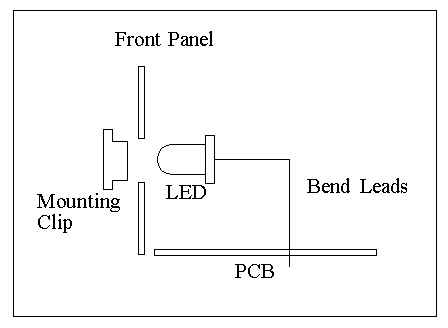
You get to mount the LEDs to the case font, and bend the leads
down to the board and solder. First, install the LED holders on
the front panel, through the front. Next, the LEDs press into the
rear of the holder. Mount the case front panel to the case half
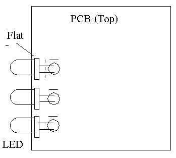
(which has the PCB). Orient the FLAT on the side of the LED lip
towards the DB-9 socket (each LED) - you will see that the PCB
silk screen also has a "dash" above the LED circle symbol
indicating the side of the flat. Bend the LED leads down to enter
the PCB holes for them - you will have to do a trial fit, then
trim the leads down a bit. Then, re-install and solder from the
top of the PCB. It is a little tricky - take your time.
Now, finally, its time to mount the FETs. If you received the plastic FET case variety (IRFIZ34N), then you are there - this is a insulated case variety, so it just mounts on the back panel. If you are using the metal-tab TO-220 type (IRFZ34N), then you need to use a mica insulating setup to prevent the tab from touching the metal case back.
The FETs mount on the back panel, held in with nylon
screws/nuts. Be sure to apply heat-sink compound. The leads are
bent out from the FET at a 90-degree angle, then bent down to
enter the holes.
Here is a drawing
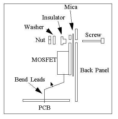
for the FET mounting, depicting the mica insulators for the metal-tab FET type - for the plastic-tab variety, just use the nylon screw (no mica or insulator), but follow the bending of the leads into the PCB as shown.
Wow! 73 steps to success! It's time to test it all. Plug in the processor, DB-9 cable, and stimulator. Now, you should see the injector LEDs on the stim board light up, tracking the RPM. Also, the fuel pump light should be glowing, and if you are above 500 RPM (see the Runtime display) and below 160 degree coolant temperature (adjust on the stimulator), the fast-idle LED should also glow. If this is the case, you are golden. Stick the unit in the car, tune, and go.