One of the more challenging engine interfaces to the MegaSquirt-I™ ECU is the tachometer input. There are many different ignition combinations on the road, each of which pose their own unique situation - even two identical engines with identical ignitions may require different tach setups. This is the one part of the MegaSquirt ECU where you may have to try different configurations for optimum performance. Below is a discussion on different tach interface techniques, and some alterations that are suggested in order to get the required MegaSquirt-I™ trigger signal.
Also, before you begin your tach interface, make sure that your ignition is in optimum condition. Check your wires, plugs, rotor, coil, etc. - a bad component can cause false MegaSquirt-I™ triggering. When in doubt about a particular component, replace.
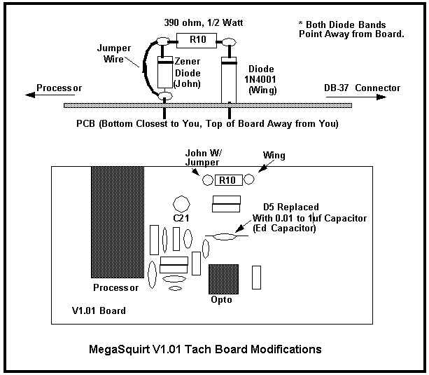
Also, in place of D5 install a 0.1 µF capacitor (known as the Ed capacitor). The illustration shows a 0.01 µF capacitor, but start with a 0.1 µF.
Here is the complete modification:
Try this combination first and perform a datalog of the engine running and under idle and acceleration conditions. If the RPM is consistent from point to point, then this tach combination will work. If the RPM jumps around, then you will need to do a little experimentation. Also, look at the seconds column. It should count up until it reaches 255, then it will roll over to zero and start back from there - this is normal. If the seconds rolls back to zero before reaching 255, then the MS box has experienced a reset and you need to run a separate return wire back from the opto-led.
If the RPMs jump around, then first try increasing the Ed capacitor from 0.1 to 0.22 µF, then 0.47 µF. If the MegaSquirt does not trigger (watch the trigger LED on the front panel), you may have to lower this capacitor to 0.01 µF. In most cases, the proper selection of the Ed capacitor will clean up the RPM spikes by low-pass averaging the ignition coil signal.
If changing the capacitor value does not help, then you need to address the resistor. First, raise the value from 390 Ohms to 1K Ohm, 1/4 watt, and run the engine. If this makes the RPM worse, then try a 330 Ohm, 1/2 watt resistor. Also, if your factory tach stops working, then you may need to increase the resistor value to 1K Ω, or even 2.2K Ω. If there are still tach triggering problems, you can install the "Dave Capacitor". Get a 0.22 µF capacitor (rated to 100 Volts or higher) and place one lead at the junction of the 390 Ohm resistor and the Wing diode, and the other lead to ground. For many installations this does the trick.
If you still experience problems, then cut the jumper on the John Zener diode and try the above sequence again. If you cannot find a resistor or capacitor value which works, then you may want to try taking the signal off of the VR or Hall sensor - see section on Hall/VR Triggering below.
For a Hall sensor, the setup is easier. Most Hall sensors use a open-collector NPN transistor (emitter tied to ground), so you can use this point to tap a signal for the MegaSquirt® tach. Use a 1K Ω resistor for R10, and jumper out the John Zener (keep the Wing diode). If you experience problems starting, then increase the resistance of R10 to 2.2K Ω. You may also have to add a pull-up resistor to the tach signal - use a 10K resistor tied to +12V.