You may also wish to build up the connector from multi-conductor cable, instead of individual wire runs - once again, your choice. Also, if you are triggering the MegaSquirt® from the negative-terminal of the coil (-), then you may want to use a shielded wire for this (there have been reports from the field indicating that shielded cable helps reduce false triggers - this makes sense, the coil primary circuit deals with high potential spikes). Also, if you are triggering off of the coil primary, you may want to run the opto-isolator circuit return thru the shield - connect the shield to one of the unused jumper locations, like X11 (pin 25) - be sure that there is a jumper on the MS ECU board from terminal XG1 to the terminal you choose for the return, like X11. Note that the X jumpers are brought out on the relay board terminal strip as "S" terminals, i.e. X11 is brought out to "S1", X12 goes to "S2", etc.
Finally, for some installations, it may be desired to run the cable through the firewall, and assemble the connectors on each end (one inside of the passenger compartment, the other inside of the engine compartment). If you do this, be sure to connect one wire at a time, on both ends, to make sure the wiring order is maintained correctly.
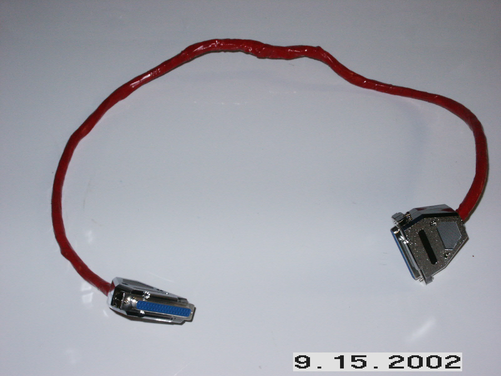
1) First, find locations to mount the MegaSquirt® ECU and the relay board. The MS should be mounted away from excess heat, like in the passenger compartment. The Relay Board can be mounted in the engine compartment, or in the passenger's compartment next to the MegaSquirt® ECU. With both boxes mounted, measure the distance between them from DB-37 connector to DB-37 connector - this will be the length that you will cut the individual wires.
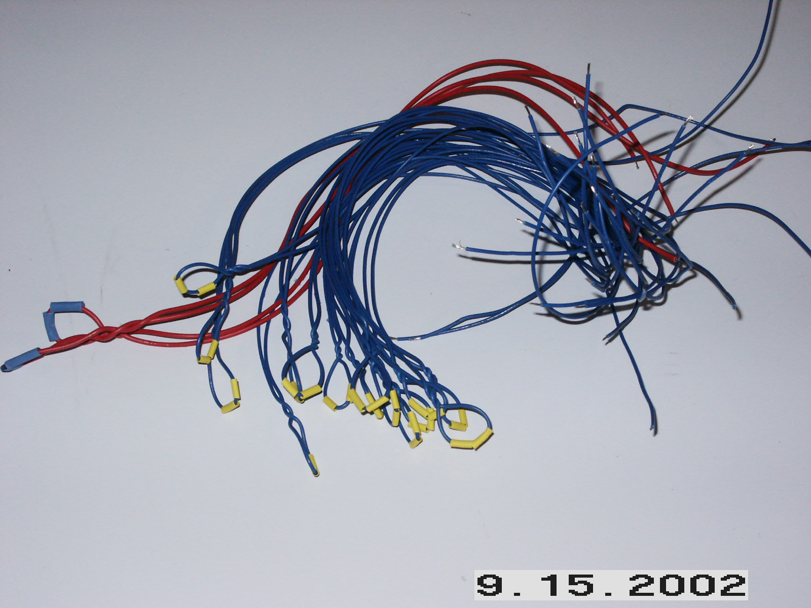
2) Purchase enough wire for the distance - you will need 16 to 21 wires (I use 20 gauge) for the sensors, relays, and power, and two 14 - 16 gauge wires, one for each injector bank. Also purchase some heat-shrink tubing which you slip over the soldered connection and shrink. I recommend cutting and stripping each wire ahead of time, and cut 1/2 inch (12 mm) lengths of heat shrink tubing and run two each on each wire, one for each end. What I like doing is moving both heat shrink tubing pieces to the center of the wire length, and then twisting the center of the wire with a few twists to hold the heat shrink in place, so that it does not fall off the wire or run down while soldering the connection. Click here to see the wires!
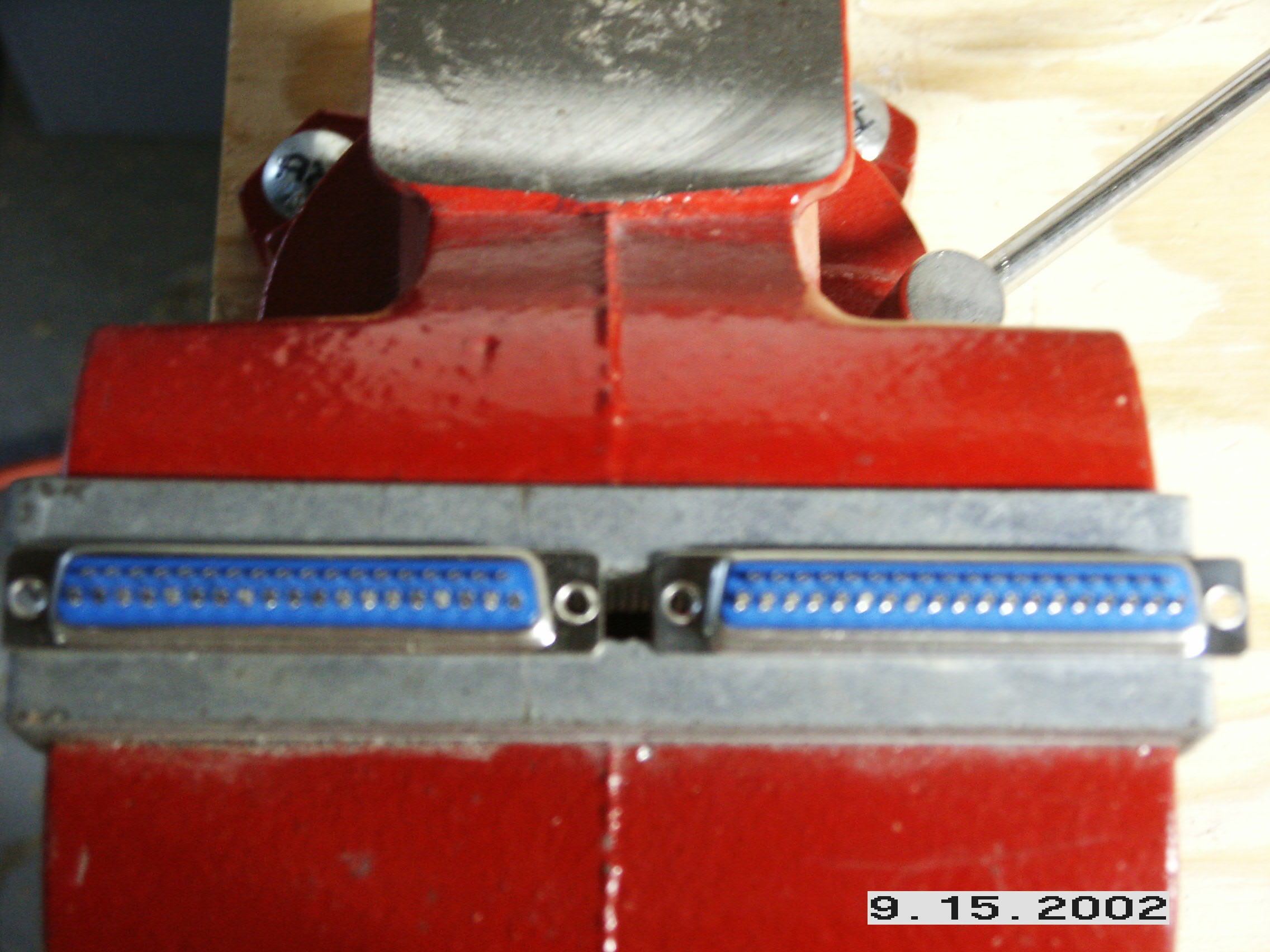
3) Find a vise and place the two DB-37 wire connectors, solder-cups up. Orient them so that both are facing the same way, with pins #1 - 19 closest to you - click here to see what I mean.
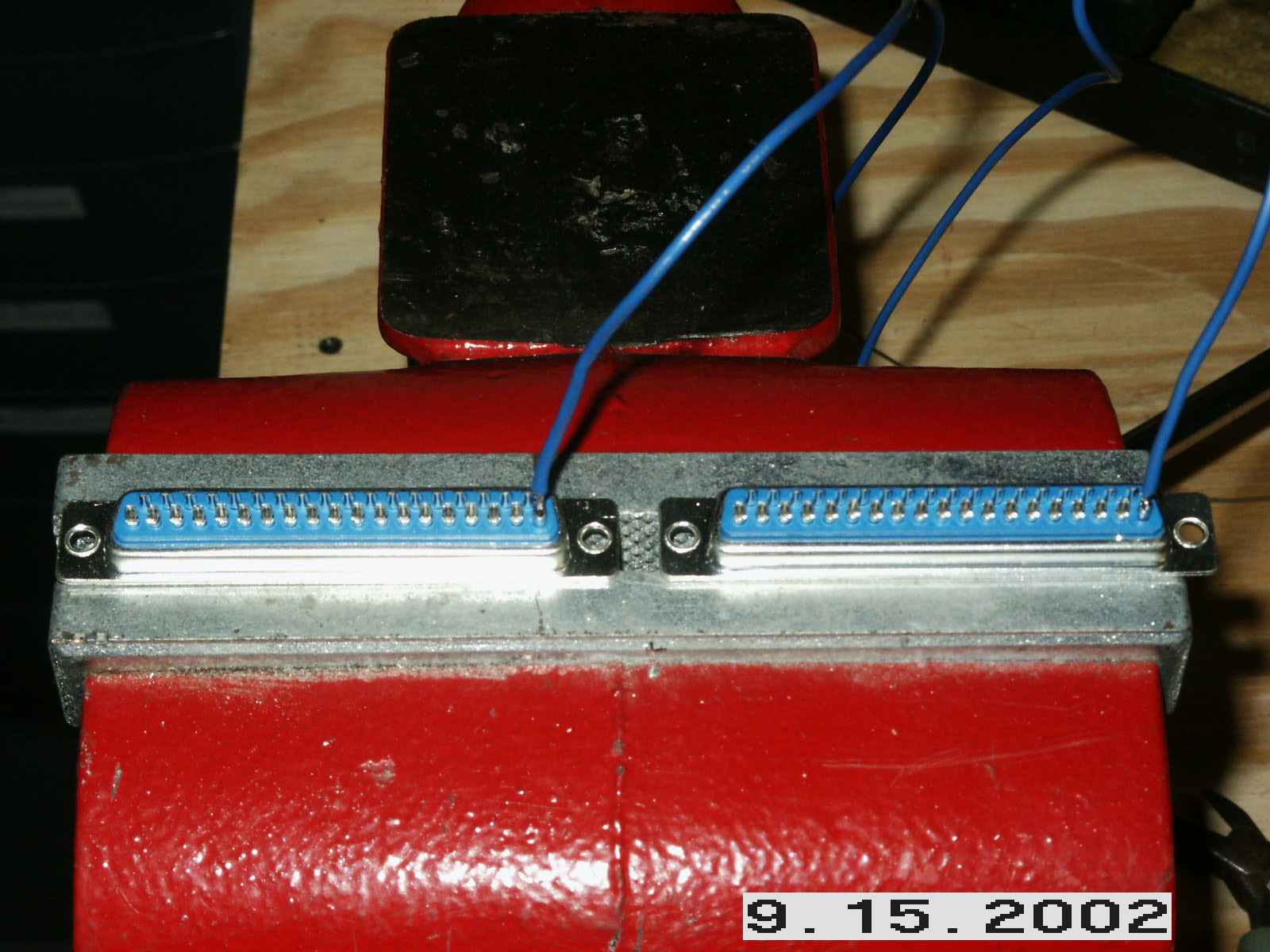
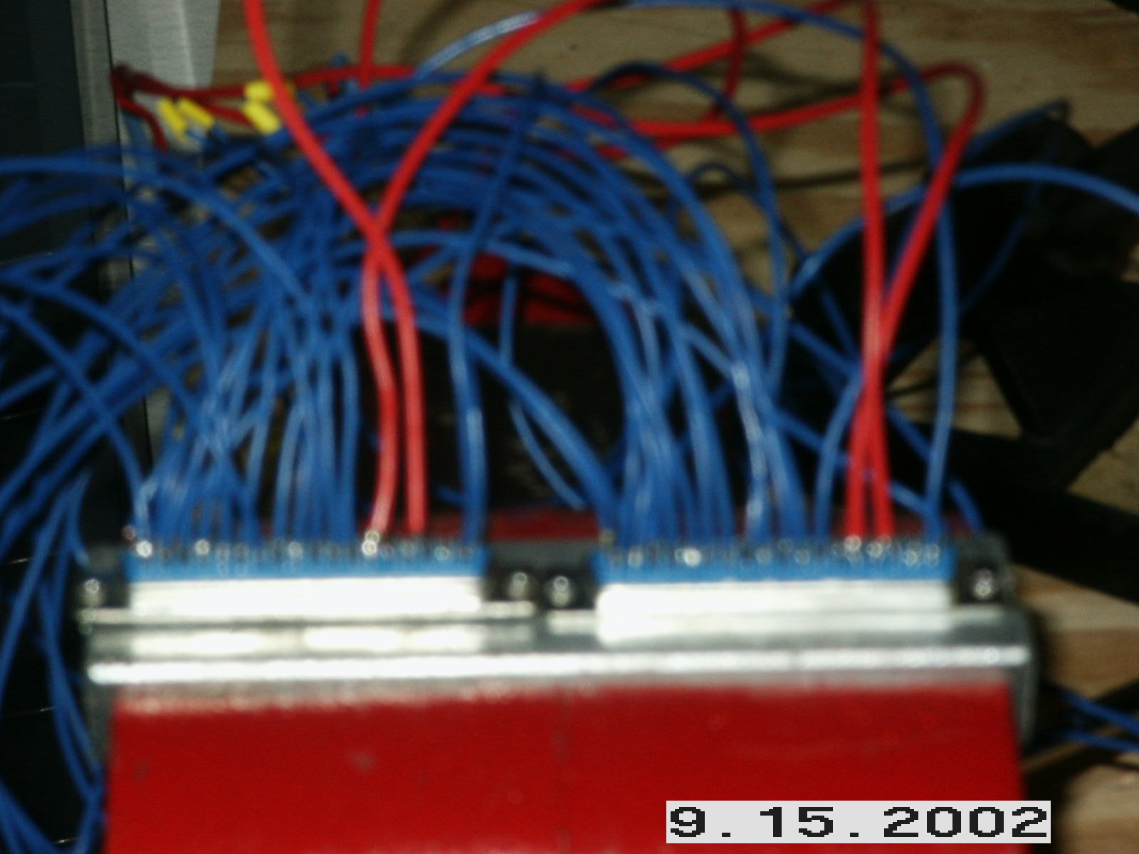
4) Now, you are going to affix one wire at a time (20 ga.), starting with the ground wires. Run one wire from pin #7 to pin #7 (there are numbers on the connectors) and solder both ends - here it is completed. Repeat with pins 8, 9, 10, 11 and 19 (this one is important - it is the return wire for the sensors). If you want to run more ground wires from pins 12 - 18, you may do so - I find that five (plus the sensor ground) is enough, but run more if you like (it cannot hurt). Note that each connector looks the same as the other - one pin to one pin. When you are done, it will look like this.
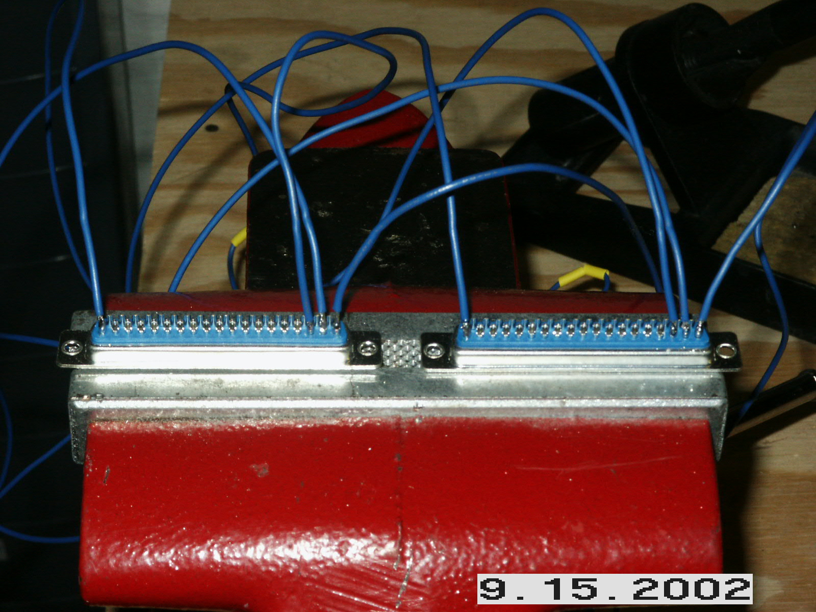
5) Now, turn both connectors around, and start wiring away. You are gong to run the 20-gauge wires from pins starting with pin pin 20 through to pin 37, and the 16-gauge wire from pins 32/33 and 34/35 for the injectors.
The pin functions for MS-I/MS-II are:
| DB37 pin #1 | ground/not used |
| DB37 pin #2 | ground/not used |
| DB37 pin #3 | SPR1 (CANH) |
| DB37 pin #4 | SPR2 (CANL) |
| DB37 pin #5 | SPR3 |
| DB37 pin #6 | SPR4 |
| DB37 pin #7 | Ground |
| DB37 pin #8 | Ground |
| DB37 pin #9 | Ground |
| DB37 pin #10 | Ground |
| DB37 pin #11 | Ground |
| DB37 pin #12 | ground/not used |
| DB37 pin #13 | ground/not used |
| DB37 pin #14 | ground/not used |
| DB37 pin #15 | ground/not used |
| DB37 pin #16 | ground/not used |
| DB37 pin #17 | ground/not used |
| DB37 pin #18 | ground/not used |
| DB37 pin #19 | Sensor Ground |
| DB37 pin #20 | Intake Air Temp. (IAT) sensor |
| DB37 pin #21 | Coolant Temp. (CLT) sensor |
| DB37 pin #22 | Throttle Position sensor (TPS) |
| DB37 pin #23 | EGO (O2) sensor |
| DB37 pin #24 | Tach (Ignition Input) |
| DB37 pin #25 | IAC 1A |
| DB37 pin #26 | Vref (+5V output) |
| DB37 pin #27 | IAC 1B |
| DB37 pin #28 | +12V Supply |
| DB37 pin #29 | IAC 2A |
| DB37 pin #30 | Fast Idle (FIdle) |
| DB37 pin #31 | IAC 2B |
| DB37 pin #32 | Injector Driver #1 (INJ1) |
| DB37 pin #33 | Injector Driver #1 (INJ1) |
| DB37 pin #34 | Injector Driver #2 (INJ2) |
| DB37 pin #35 | Injector Driver #2 (INJ2) |
| DB37 pin #36 | Ignition Output |
| DB37 pin #37 | Fuel Pump (FP) |
If you are planning to use any CAN enabled boards to communicate with other CAN boards (like the GPIO board), you will also want to add wires on pins 3 and 4 for the CANhigh and CANlow connections. Only connect these at the MegaSquirt® end of the cable, the loose ends will go to the other controller.
What I did with these is split the stripped wire ends into a "fork", and stick then in the adjacent holes 32 and 33, and solder, doing the same for 34/35). Note that the wire for pin 36 is for the ignition output with MS-II. Run each of these one at a time, starting with pin 20 to pin 20, then another wire from 21 to 21, etc. Looks like this when done. And, if you are using shielded wire for the coil (like RG-174 or audio cable), the center lead connects to pin 24 and the ground to pin 25 - make sure you run a wire from the terminal strip "S1" terminal to engine ground.
6) Next, unwrap all of those loops on the wires holding the heat shrink in place, and work each piece to each end of the connector, and shrink the tubing down with a heat gun, or even a lighter. At first, the wires will be a tangled mess, but when you start working the shrink tubing to each end, the kinks will work themselves out.
7) Finally, wrap the wires in electrical tape from connector to connector. Here it is all finished - the wiring will be slipped inside of a wire loom after being installed in the vehicle. An alternate way of bundling the cables is by using a large-diameter heat shrink tube, and run each wire inside of this large tubing when making up the connectors, then finally shrinking the entire piece down.
8) Now, you can connect the cable to both the MS ECU and the relay board. Apply +12V to the "12 Batt" pad lead, and return battery to "Engine Ground". If you jumper the "Switched 12V" to the "12V Batt" pad, you will hear the main relay kick in, and the MS will power up. Keep this jumper connected. Next, fasten down a wire to the "Tach" terminal on the relay terminal strip, and touch this to the +12V source (or use the "Injector +12V" terminal strip) - each time you touch it, the tach trigger LED on the MegaSquirt® ECU should flash. Also, the first time you do this, the fuel pump relay should click-in, and it will stay in as long as you keep on touching/releasing the tach wire (i.e. pulsing the circuit). After two seconds from when you stop pulsing the tach circuit, the fuel pump relay will de-energize. Next, hook up the sensors, e.g. hook the coolant sensor between the "CLT" and the "CLT Ret" terminals, which are the Coolant and Coolant Return. Do the same for the MAT and TPS (the TPS connectors to the "Vref", "TPS" and "TPS Ret" terminals). For each of these, run the PC Configurator and verify that these are working. For the O2 sensor, touch a jumper wire from the O2 to the "Vref" terminal (*NOT* 12 volts or injector +12V) - check on the PC Configurator for O2 sensor voltage.
To check the injector drives, you can use the injector themselves, or use a taillight bulb for this - connect from the "Inj1" to the "Injector +12V" terminals, and repeat for the "Inj2" side as well. For the fuel pump, hook a taillight between the "FP" terminal and ground - it should light when you trigger the tach wire.